Intermediate Heat Exchanger
This section is essentially a copy
from an article that has appeared much earlier in the old sci.math and sci.physics groups.
Problem: how to describe the complex transport phenomena in the flow around the
tubes of a shell-and-tube heat exchanger, such as the one depicted below.
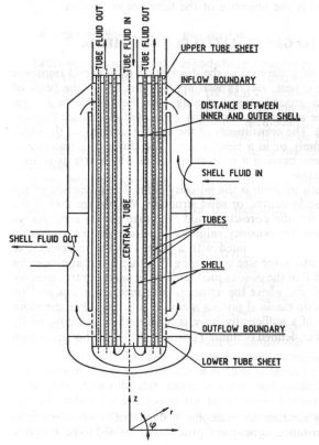
A heat exchanger is a container with many (straight) tubes mounted in it.
The container is filled with a medium which is called the primary or shell-side
flow. The tubes are filled with a medium which is called the secondary or tube-side flow.
The primary flow is "hot" while the secondary flow is "cold". The primary flow streams from
top to bottom while the secondary flow streams from bottom to top. In this way, the secondary
flow is heated up by the primary flow. Which explains the device's name.
The flow-distribution on the shell-side of a heat exchanger has a significant influence
on the temperature distribution across the tube-bundle and consequently on the thermal
stresses caused by temperature gradients.
Fluid-Tube Continuum
In order to describe the shell-side flow and temperature distribution, investigators have
attempted the so-called fluid-tube continuum approach. The idea of the method is: setting
up partial differential equations for a kind of porous medium. Tube bundles are treated
this way because, from a practical point of view, it is hopeless to apply the basic laws
of flow (Navier Stokes) and of heat transfer directly, without approximations. (Requiring
for example that velocities should be zero at all parts of the solid structure.)
Classical theory of porous media describes flow and transport through soils, consisting
of sand, clay, peat. Typical applications are in the field of petroleum reservoir
engineering and groundwater hydrology. But looking around, we can see many non-classical
examples of transport phenomena where porous media are involved. Such as potatoes, stored
in a vessel, which form a porous medium for the cooling air flow. Other examples are
filtration, chemical reactions using solid catalists, adsorption, and mass transfer in
packed columns. Finally, the flow in the core structures of nuclear reactors, rod arrays,
and also heat exchangers can be considered as a flow in a porous medium.
Before proceeding further, it is important to realize that there is nothing
fake in considering tube bundles as true continuous media. In my (not so)
humble opinion, the Fluid-Tube Continuum is in no way different from other
continuous media, like rock, water, air or even space-time itself. Physics
allows continuous media only to exist by approximation. Which is due to the
fact that "real" numbers, covering observations, are essentially inaccurate.
As far as the fluid-tube continuum in a heat exchanger is concerned, that inaccuracy
has as an order of magnitude the distance (pitch) between two adjacent tubes.
Governing Equations
It can be argued that, as a first approximation, the shell-side flow in the tube
bundle is not only incompressible, but also irrotational. The latter
can be understood intuitively. The size of a fluid particle in the fluid-tube
continuum model is, "by definition", greater than (say) the pitch between two
neighboring tubes. It is reasonable to assume that a fluid particle of this
size will experience almost equal friction at all of its sides, and therefore
will not rotate. Consequently, the (Partial Differential !) equations for flow
in a tube bundle may be assumed to be those for ideal flow,
in a cylindrically symmetric geometry:
$$
\frac{\partial ru}{\partial r} + \frac{\partial rv}{\partial z} = 0
\qquad ; \qquad
\frac{\partial v}{\partial r} - \frac{\partial u}{\partial z} = 0
$$
Here: $u$ = horizontal velocity component, $v$ = vertical velocity component,
$r$ = horizontal radius, $z$ = vertical distance.
By assuming Ideal Internal Flow, the flow field is invariant
for scaling with a factor $G_P$ (independent of the flow magnitude) and therefore
will be normed in such a way that the absolute vaule $\left|(u,v)\right|$ is unity
$= 1$ in the middle of the bundle. Furthermore,
the Neratoom
heat exchanger has been designed in such a way that the flow velocity in the middle
of the bundle is the same as the flow velocity at the inlet perforation. So Ideal
Flow calculations, with $u = -1$ at the inlet opening, can immediately be used
and only have to be scaled to describe the real thing. So far so good for the flow,
which is ideal in more than one respect.
Now wrap a control-volume around a couple of tubes. Set up the energy balances for
this volume. Let the volume become "infinitesimally small", though still remaining
larger than the distance between the tubes. Or throw away the integral signs
after applying Gauss theorems. Or whatever. Then the following set of Partial
Differential Equations may be inferred for Heat Exchange in a tube bundle:
$$
c.G_P \left[ u.\frac{\partial T_P}{\partial r} + v.\frac{\partial T_P}{\partial z} \right]
+ a.(T_P - T_S) = 0 \qquad \mbox{: shell side} \\
c.G_S.\frac{\partial T_S}{\partial z} +a.(T_S - T_P) = 0 \qquad \mbox{: tube side}
$$
Here: $c=$ heat capacity; $G=$ mass flow; $T=$ temperature; $(r,z)=$
cylinder coordinates; $(u,v)=$ normed velocities; $a=$ total heat
transfer coefficient; $P=$ primary; $S=$ secondary.
The boundary conditions should not be forgotten:
$$
T_P = T_{PL} \qquad \mbox{at the primary inlet (upper perforation)} \\
T_S = T_{S0} \qquad \mbox{at the secondary inlet (tube plate below)}
$$
Remember. These equations are ONLY simple and elegant because very CRUDE
approximations are involved. Replacing the Discrete (tubes in fluid) by an unstructured
amorphous mixture of fluid and tubes means that a lot of (useful?) information has been
simply thrown away, for the purpose of the end-result being applicable in engineering.
The system of Partial Differential Equations has served as an analytical framework whereupon
Numerical
Methods
can be based. Like making powder from potatoes, and then preparing potatoes
from the powder again (-: S.V. Patankar).
Reference (somewhat outdated):
H. de Bruijn and W. Zijl; Numerical Simulation of the
Shell-Side Flow and Temperature Distribution in Heat Exchangers;
Handbook of Heat and Mass Transfer; chapter 27; Volume 1: Heat Transfer Operations;
Nicholas P. Cheremisinoff, Editor; Gulf Publishing Company (1986).
Continued with: